Voltage multiplier circuits are electronic circuits that multiply the input voltage 2 to 3 or 4 times, and the output voltage RMS is also 2 to 4 times higher. This kind of circuitry basically employs just some diodes and capacitors. It takes AC input and then converts that to higher Amplitude DC voltage. The voltage multiplier is made up of capacitors. The voltage multiplier circuits have different stages. Each stage uses a diode and a capacitor. This type of connection of diodes and capacitors makes it possible to produce rectified and filtered output voltage whose amplitude (output RMS) is larger than the input AC voltage.
Voltage multiplier circuits are of different types:-
- *Half-wave voltage doubler
- *Fulwave voltage doubler
- *Voltage tripler
- *Voltage Quadruple
I have discussed two voltage multipliers in this article. One is, voltage doubler and the other one is a Voltage Quadrupler.
Voltage Doubler

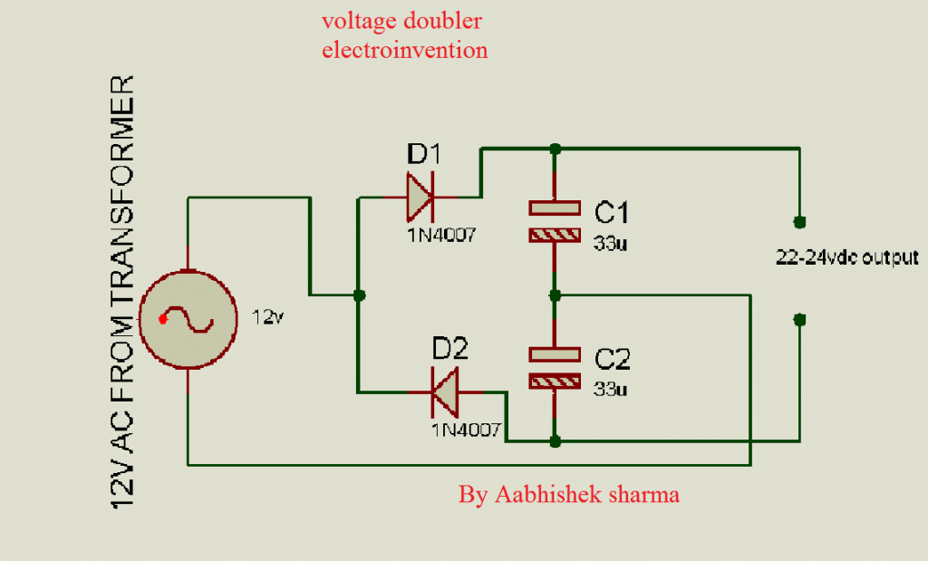
When AC enters, During the positive half cycle the D1 is forward biased and C1 is also charged with the rectified output and its negative goes to the negative cycle. During the negative half-cycle, diode D2 is forward biased and C2 gets charged, this process goes on so fastly at 50-60hz frequency speed and output is taken from both capacitors connected in series.
so we get a doubled output 2*12v =24v approx. output. Since output voltage increases the output current decreases but power always remains the same.
Voltage Quadrupler

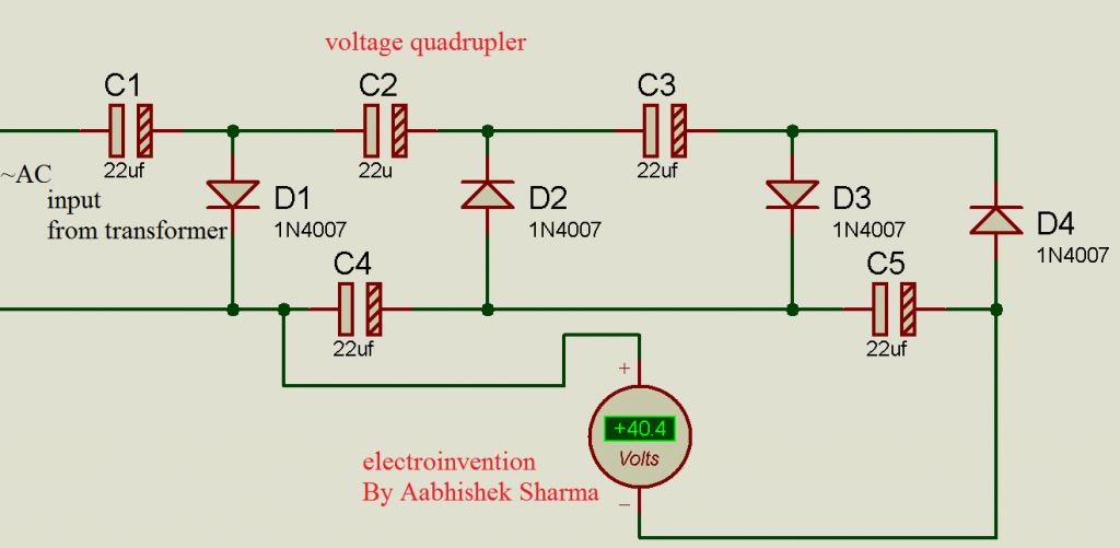
Here is the voltage quadrupler with more capacitor and diode multiplier stages to give a 4*12v=40 to 48 v dc output.
Always with an increase in output voltage, the output current is decreased. But the total power remains approximately the same as the input.You can also follow these cicuits shown in images as they are tested by myself and designed and simulated.
I hope you guys liked it, for any queries comment below and let me know.


Thanks for clearing