
Hello Engineers. At places like small gatherings or meeting halls, small conferences, and classrooms it’s good to employ a visitor counter. This visitor counter circuit will count the visitor number of persons entered in the room or hall. The circuit explained in this tutorial today, is using two CD4026 ICs with two 7-segment LED displays. This Digital visitor counter circuit can go up to 99 counts. As soon as a person enters the room, the counter value increments by 1. So, let’s start with our topic Digital visitor counter circuit.
7- Segment LED Display
A 7-segment display module is an electronic device to display letters, digits, and numbers. These are the modules that are mostly used in devices such as electric meters, voltage stabilizers, test instruments, etc. Instead of the complex dot matrix displays, they are better and easier. They have separate seven segments that help to make a letter or number. 7 segment displays can have an LCD (Liquid Crystal Display) or LED (Light Emitting Diode) for each segment. A-F are markings for the individual components. They can be of 2 types. 1. Common Anode and 2.Common Cathode.
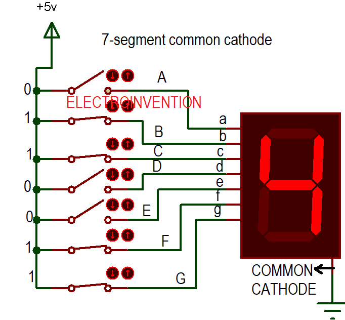

1.Common Anode – This means all anodes of each LED are common. To display a number or a letter we need to give ‘0’ or – ve to selective LEDs segment according to the code.
2.Common Cathode – All the cathode of each LED segment is taken as common and only ‘1’ is given to those LED’s anode that helps us to make our specific letter.
IC CD4026
IC CD4026 is a CMOS 4000 series 7-segment counter ICs and operates on very low power. This decade counter IC can count from 0-9 on a 7- segment common cathode display. We are going to use it in our visitor counter circuit today with the seven-segment display. Below are the circuit diagram as well as explanations and working.
PINOUTS
1. CLOCK PIN (CLK) – This is the pin number 1 which takes clock input. As soon as the clock pin goes high, counts are incremented.
2. Clock Inhibit(INH) – It’s the PIN number 2 and it should be low ( ground) to enable the clock pin pulses.
3. Enable Pin( DEI) – This is PIN 3, it should be kept high(+5V – 9V) so as to enable the output pins A to G.
4. DEO pin – PIN number 4 it’s always high(+5V – 9V) in case if we more than 1 CD 4026 IC.
5. CO pin – PIN number 5, used for cascading: i.e carry forwarding the counting by using another IC.
6. PIN 7 to 13 – These are all output PINs that provide decoded output.
7. VSS pin 8 – Ground.
8. PIN 14( UCS)- Unused. Only used rarely for the division.
9. MR – PIN number 15. Memory reset or resetting the counter to start from 0.
10. VDD or VCC – This PIN powers the IC. (5V – 9V).
Circuit Diagram for digital visitor counter

Materials
- R1 – 10K-12K ohms – 1pcs
- R3 – 47K to 50K -1pc
- R2, R4 100ohms – 2pcs
- IC CD4026 – 2pcs
- 7-segment display common cathode (buy 5 Pieces @ $ 2.64 i.e Rs 200 INR)- 2pcs
- Also check Buy 7 segment display common cathode for Rs.11 per pcs cheap, can buy in bulk also
- LDR 1M – 1pc
- 9V Battery
- 16 pin DIP connector( for ic base on PCB) – 2pcs
- PCB
Working for Digital Visitor Counter
As shown in the circuit above, there are two 4026 decade counter ICs first one having a primary clock input and the second one having cascaded to the previous stage. Also, there are 2 common cathode LED displays, one with each IC.
The Laser light is continuously striking the LDR unless or until someone doesn’t cross by through it. So, as we know with the intensity of light the LDR resistance is very low. This makes the base connected to the ground and shorted by the emitter. When someone crosses between the path of the laser, the light is absent for a second and resistance of LDR is very high(1M). This makes the base to get adequate supply and transistor is ON. This makes IC get clock pulse input via CLK pin and the counter is incremented with output displayed on the LED display. After that same thing goes on and on till 9.
IC 1 PIN number 5 ( CO) output goes to PIN 1 of IC2 as the clock pulse input. It is for carry forwarding of bit that goes to another counter. Once the previous counter counts up to 9 and resets to 0, the carry-out pulse is forwarded to the 2nd decade counter.
Display 1 shows the digit 1 and displays with IC2 shows digit 0, it starts with 10 now. This same process of carry-out goes on and on between IC s. Common PINs of both displays are connected to ground as its common cathode. Max. count by this counter can go is the largest 2 digit number 99.
So, guys, I hope you liked it. Let me know in the comments section about any queries or doubts. Thanks. Subscribe to our newsletter for the latest post updates.
Wow, this post is nice, my sister is analyzing these kinds of things, thus
I am going to convey her.
Many thanks to you, a very relevant note.
Oh my goodness. Impressive article dude.
Cool..I want to read even more things about it!
Good post. I was facing many of these issues as well..
VERy nice broo
Thanks for visiting bro
Pretty! This has been a really wonderful article.
Many thanks for providing these details.
nicw
I good article
thank