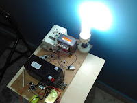
Hello, everyone the instructable here in this post is a 60watt homemade inverter. Inverters are of 2 types mainly square wave and sinewave. The design discussed here is a powerful 12V- 220V AC inverter, 60w square wave inverter. This inverter is capable of powering CFLs, tube lights, dc fan ext. it can handle up to 150W. Even you can charge your laptop and mobile. Powerful 12V-220V AC inverter. DC 12v to 220v ac inverter.Simple inverter circuit. Powerful 12V-220V AC inverter
Note: this is a 220v, 50Hz square wave inverter
INVERTERS ARE DEVICES THAT CONVERTS 12V OR 24 V DC VOLTAGE FROM A BATTERY TO AC AND PROVIDES US stepped up output as 220V/110V AC.SUPPLY DURING THE ELECTRICITY CUTOFF(also known as UPS).
How does an inverter works?
DIFFERENT POWER STAGES / COMPONENTS OF AN INVERTER
1.INPUT STAGE:- An inverter requires 12v DC or 24V DC input from a powerful long-run battery with sufficient amperes ratings according to the power requirements.
2.DC TO AC CONVERSION OR OSCILLATOR STAGE:- In this stage, the dc input from the battery is converted to AC via an a-stable Oscillator circuit. An oscillator is a device or a circuit that converts unidirectional current flow from a DC source like a battery to an alternating waveform of some desired frequency.
3.STEP UP OR VOLTAGE STEPUP STAGE:– After the DC has been converted to AC, now the converted ac voltage needs to be stepped up to 220/110v ac for domestic use. THIS COULD BE DONE USING A POWER TRANSFORMER THAT COULD BE ENOUGH TO HANDLE THE LOAD.
MATERIALS AND COMPONENTS:-
- Transistor 2n2222a or BC547 -2pcs
- capacitor 1uf – 2pcs
- MOSFET IRF540N – 2pcs
- 12v 10 or 7.6 AH Lead Acid battery
- 12-0-12 5AMP To 10Amp Transformer
- heat sinks – 2pcs separately used for both MOSFETs
- RESISTOR(R2&R3) 12K or 10k – 2PCS
- RESISTOR(R1&R4) 680 Ohm – 2 pcs
- Misc : wires,tapes,switchboard ,battery clips,multimeter,soldering iron,etc.
- GENERAL PURPOSE PCB – 1 pcs
- Transformer 12-0-12 5amp to 8amp. will be used as reversed for a step up
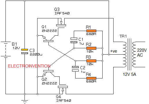
THE CIRCUIT DIAGRAM

How does this inverter works
- The design here is using an astable multivibrator (also known as a free-running oscillator) as an oscillator for generating square wave pulses at a 50-60hz frequency,
- The square wave pulses generated from low power 2n2222a transistor are fed to N-CHANNEL MOSFETS for amplification of power. Finally, the generated AC POWER is fed to the 12v side of the power transformer and stepped up to 220v or 110v ac (as per your country specification).
- I have also employed a battery charging circuit(about which we will discuss some other day) in this that can charge the battery effectively. This inverter is not designed to have an Auto cutoff feature.
- The circuit discussed here has a maximum rating of 60 watts load if you use 12-0-12 5 ampere transformer and 90 watts max if you use 12-0-12 8 Amp transformer.
- Even though the 60 watts design is enough to operate most of the CFLs, Tubelights, Table fans, Mobile phone chargers, etc. for a long duration.
- After you have made the circuit as shown in the diagram, then connect the battery input as shown in the circuit diagram and test the output voltage with an AC voltmeter OR a Multimeter. If it shows 220v to 230v AC output then your inverter is good and then try to connect a 15w CFL or any bulb or mobile phone charger to test whether the inverter is serving its purpose or not. Never exceed the MAX. rated wattage of an inverter.
*SOME KEY POINTS*
- *INPUT POWER = OUTPUT POWER
- *OUTPUT POWER = VOLTAGE*O/P CURRENT across device
- *Backup time depends upon Battery ah value as,
- *Total available power(Ah*Vin) / load power requirement=backup time(in hours)
- * Output VOLTAGE INCREASES, CURRENT DECREASES
these are key points
NOTE:- THE CIRCUIT DIAGRAM HERE IS PRACTICALLY TESTED BY MYSELF AND WORKS PERFECTLY.
ALWAYS BE SAFE, MAKE SURE YOU never HURT YOURSELF OR ANYONE ELSE.
AC MAINS VOLTAGE ARE VERY DANGEROUS, BE SMART, BE SAFE.
If you guys liked this article then please mention your views in comments. If there are any kind of doubts or suggestions then please comment them below.


What if I want 100 watts with dis inverter design. What will be the transformer and battery specs. I want to run 2 Led bulbs 10w for 7 hours. and sometime a mobile charger which is maybe around 5 wats.Thank you
Hello Kapil,
1. If you want 100w with this design then you have to use a 12-0-12v 10Amp transformer and 10Ah which will give you 120watts but for safety practically never exceed above 100w loads.
2. You want to run 2*10w LED bulbs for 7 hours and a mobile charger 5watts, so the total load requirement is 25watts/hour. For that 100watt inverter, design is enough, but for running it 7 hours you’ll need to have more backup. I prefer you need to use a 12v 20Ah battery that will have a backup of 240w and can run your 25watts load even more than 7 hours.
Thank you for visiting.
Really awesome bro make some more project very nicely explain thanks bro
hello,tushar thanks for your appreciation.stay tuned new posts are comming.
Bro make some more project like these i poke your project very much and thanks tou very much for making these blog and my all doubt are cleared here ?
thanks brother
Tushar do u know tesla ?
Hallo bro