PIR motion sensor light. Hello engineers, sometimes it’s a bit difficult to go in a dark room and find a light switchboard to turn ON the lights and it’s sometimes lazy too to switch on and off the lights when going in or out of the room each time or going through the garage or parking lawn. So today I am going to discuss a simple motion detection Light/ PIR motion sensor light system without using any microcontroller like Arduino, AVR, etc, or complex circuitry. Just a simple motion sensor light using the PIR motion sensor light /Automatic motion sensor light circuit. So, let’s discuss it further.
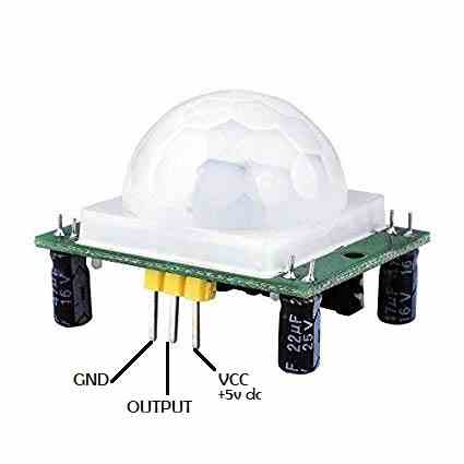
PIR motion sensor
PIR or Passive Infrared Sensor is a kind of electronic sensor that is used to detect the motion sensitivity. It basically measures the infrared light radiating from surrounding objects under its scope of visibility.

PIR sensors do not emit any energy or rays, instead, it detects the infrared radiations emitted by or reflected by surrounding objects. All living or non-living beings having a temperature above absolute 0 emits heat in the form of radiation. A PIR sensor is used for detection of motion by Objects, human beings, animals, etc any kind of movement by any entity.
A PIR requires an input voltage of 3.5v -5v dc at the VCC pin to operate and it gives a TTL( Transistor-Transistor Logic) output directly to the microcontroller’s pin or to the relay driver transistor when it senses motion in its proximity.
PIR’s range of sensitivity and its delay time can be changed and set by the potentiometers premounted on its PCB.
The proximity range or visibility range of a PIR sensor is 120′-140′ degrees.
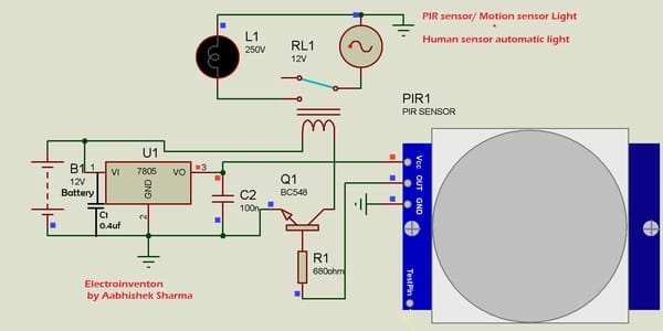
The circuit Diagram for motion detection light

Components required
- C1 – 0.4uf ceramic capacitor-1pc
- C2 -100nf ceramic capacitor-1pc
- U1 – LM7805 voltage regulator-1Pc
- Q1 BC 548 transistor 1pc
- R1 680ohm – 1K ohm resistor-1pc
- PIR motion sensor -1pc general purpose
- RELAY RL1 12v -1pc
- PCB standard size
- Bulb holder/CFL lamp holder (to mount the AC 220v Bulb or CFL/led bulb,etc)
- 12 V battery -1pc (any ah value)
How does Motion sensor light works?
In the circuit above the VCC pin of the PIR sensor is getting 5v input from the LM7805 voltage regulator and whenever the sensor senses any movement under its proximity, the output of the sensor goes to the base of BC547 transistor making it to turn ON the relay, the relay then shifts the COM pin’s focus from NC to NO pin and the ac lamp or light is then connected to 220v AC domestic supply.
When you are present in the range of PIR then it keeps sensing and keeps the relay ON by detecting continuous movement after movements in objects stop and infrared radiations reflections stops, then after completing its delay time, the PIR stops output to the transistor’s base and transistor gets turned off as turning off the relay and light’s power supply is cut.
The delay time of the sensor can be adjusted using the presets that are mounted on the PIR sensor’s PCB.
Below is a short video showing how this motion detection PIR lighting system works.


Hello, What’s the name of the software used?
ISIS professional
how to use it without a relay to power a 5 parallel 1 watt LED. I have tried to do so with a 9v battery already, but LEDs were very dim.
5 * 1watt
5* 1 watt LEDs parallel = 5 watts loads. Use a TIP122 after the BJT to drive those LEDs. It will work. if brightness is low, then try using two 9V parallel to increase backup input power.