Hello Engineers. In this article, I am going to discuss a circuit for Music reactive Dancing LED Light. The circuit need not be connected to any input signal from the amplifier. This music reactive dancing LED light circuit can listen to the surrounding music or sounds and LEDs dance according to that signal. In this circuit, we have used a condenser MIC(Microphone) to listen to the surroundings.
This is a very easy and effective circuit that requires low power. After the microphone, the Rest work is done by signal amplification and display control stage.
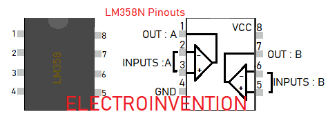
IC LM358N
LM358 is a low power dual Op-Amp Integrated circuit. According to the datasheet, it is a fabrication consisting of two independent high gain operational amplifiers.

It has 8 pins and consists of a dual Op-amp with internally frequency compensated and the capability of providing high gain. check this LM358 datasheet. Let’s move towards the circuit.
MATERIALS
- IC1 LM358N
- IC2 LM3915
- Condenser Microphone
- LM7805
- R1 10K
- R2, R3 47K
- R4, R9, R8 1K
- R5,R6,R7 100K
- C1,C3 100nf
- C2 10uf
- C4,C5,C6 330nf ( 0.33uf)
- D1 1N4148 Zener
- LEDs any color
- 9V Battery / Power supply
- PCB
- 18 Pin DIP Connector
- 8 Pin DIP connector
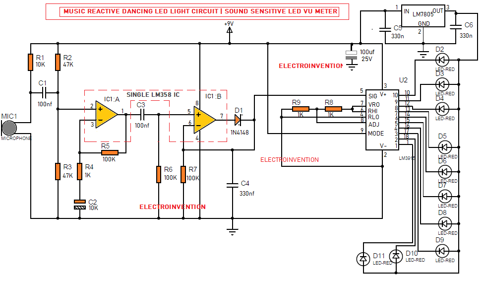
Music Reactive dancing LED lights Circuit

The circuit draws low power and can be powered by a 9v battery.
Then, R1 passes some current to MIC1 (Condenser Microphone). MIC1 receives sound and transforms them to the inverted electrical audio signals.
We know the capacitor allows AC to pass through and blocks any DC components in the signal. So, C1 passes only the AC signal to the inputs of IC1: A ( i.e 1st Op-amp of IC LM358). And, blocks any DC components in the signal.
IC1:A(LM358’s 1st op-amp), R2, R3, R4, R5, and C2 are the preamplifier to gain the signal strenghth and refining it.
The IC1: B( 2nd Op-Amp of LM358), R6, R7, D1, and C4 are then doing the task of converting the electrical audio signal to the square waveform pulses, of course in accordance to the input signal.
This signal now goes to the PIN 5( SIG) Signal Pin of IC LM3915 led controller.
We have already discussed how IC LM3915 controls the 10 LED with respect to the input signal. You can Check this VU Meter circuit using LM3915 article.
So accordingly the LEDs chase and Dance with respect to the intensity of sound and music. I hope you liked it. Tell me in comments if you need any help.
Thank You

Cool stuff sir
Its so helpful. Thanks sir