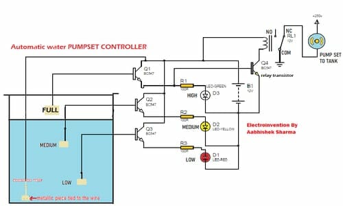
Hello engineers, Often when we turn on the water pumps to fill the water tank of our home we have to look after whether its full or not. Or even when if we have a water tank full alarm then also we have to go and turn off the pump set. So today, I am going to discuss a multipurpose circuit designed and tested by myself. It’s an ” Automatic water Pump Controller ” + additional functionality of water level detection and automatically restarts the pump when the water level goes down. When water keeps going down, the pump set continuously stays ON until the water tank isn’t full. When the tank reaches a level it cuts off the pump set’s power supply. So let’s begin with our Automatic water Pumpset controller circuit. Automatic water pump controller.
THE CIRCUIT for Automatic water pump controller

COMPONENTS
- Q1,Q2,Q3,Q4 Transistor BC547 or 2N2222A -4 Pcs
- Copper pieces – 4 pieces
- D1,D2,D3 LED- 1RED,1YELLOW,1GREEN
- PCB BOARD
- Wires 4 core
- R1,R2,R3 100R(100ohm)-3 pcs
- Relay 12V -1pcs
- 12V power supply/12V battery
WORKING of the auto-cutoff water pump controller
- The circuit diagram above is designed to have multiple functionalities like it can display the level of water up to 3 levels LOW, MEDIUM and HIGH.
- In the circuit in starting 3 levels, there is a common wire in the tank till its bed from collectors of three transistors as to show water level indication and when water touches each of the bases of transistor it completes circuit by connection of +ve and the base of each transistor and this makes LED to glow and show level of water.
- At transistor Q1 which shows tank full, its collector is connected to the green LED and also to the base of Q4 which is powering the relay.
- When Q4 gets ON, it turns ON the relay and as a result, the relay’s COM pin which was connected to the NC powering the pump via 220v AC source shifts its focus to NO(normally open)pin. Hence, the pump gets no power supply and tank filling stops.
- As the water level drops from the first level, the pump starts again to full the water tank.
- The transistors are connected as an emitter follower circuit. The transistor Q1, Q2, Q3, and Q4 can be BC547or 2N2222A or any kind of NPN transistor.
- For 4 levels use 4 core wire and cut the length of each according to the length required by level. This circuit can easily handle up to a single 1HP (1 horsepower=1000watts) motor. But do not go above 1HP motor.
- Below I am adding a video for simulation and explaining the working of the circuit.
Must watch that video.
In the video, I have used switches jut to simulate the water completing the circuit. Between each transistor’s base and common wire connected to positive. Thanks.
I hope you guys enjoyed this tutorial. Coming as soon as possible with the next tutorial keep in touch.


Hello, please is it possible to make use of a 12v or 9v DC source
Keep this going please, great job!
Thankfulness to my father who shared with me regarding this blog, this blog is truly remarkable.
very nice article thanks bro