Hello guys, today I am going to tell you an easy way to make an Automatic night light circuit(automation) without using any micro-controllers or development board. With a circuit diagram as well as a simulation video of working of this project. This is possible with a simple analog circuitry using some active components as well as some passive components working collectively. So let’s get started with Automatic Night Light circuit
So, lets first focus on the materials and components needed:-
Materials:
- Transistor TIP122 -1pc
- R1 220K -1pc
- LDR1 -1pc
- 12v relay[SPDT] -1pc
- D1 1N4007
- 12v battery
- Lamp/bulb/socket
- PCB board-1pc
- miscs like multimeter/solder,wires,etc.
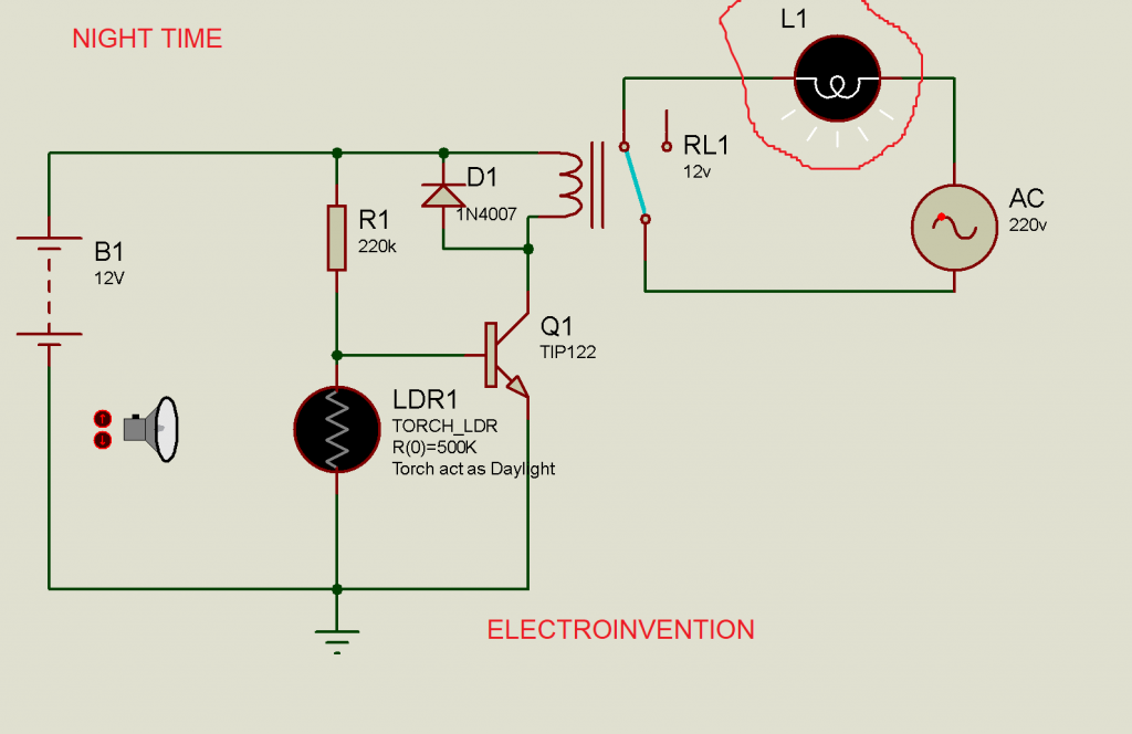
Below is the circuit diagram and its working:-
Automatic Night Light Circuit

The circuit is employing an LDR (light dependent resistor), transistor TIP122, an SPDT RELAY 12V, and a small resistor 220K as components making this circuit working.
Working step by step:-
DAY TIME OR UNDER LIGHT INTENSITY
During the day time or when the light is falling over the LDR, its conductivity increases with a decrease in its resistivity, making the transistor working as the switch is turned off by shorting the base and emitter terminal also connecting the base to the ground and as our relay doesn’t get power to its coil, so no deflection happens within the pins and lamp or light does not glow.
In PROTEUS, I have used a torch to simulate day time and turned it off to simulate LDR under dark.
For NIGHT TIME/OR IN ABSENCE OF LIGHT
When in absence of light LDR doesn’t get that much light and its resistance does not decrease. So the base and emitter are not shorted and the base separately gets +ve making the transistor ON and emitter goes to the ground. This turns the relay ON and its pin deflects and connects COM TO NO.or in simple language we can say light is turned on via relay by completing the circuit by connecting it to mains 220-230V AC.

I hope You guys enjoyed this project and have understood the concept clearly. If you guys liked it, please comment below and let me know how you felt about this project.

can you help me with analysis and description of the project . and i need a prototype
Hello Mohamed, thanks for visiting. The description of the project can be above. Regarding analysis, you have to either simulate it and also have to build one practically and check things practically.
I have a prototype version for the one using a normal NPN like 2N3904, I will upload one for this too when I get time. The circuit with TIP122 solves the clicking issue which is sometimes faced sometimes.
Although both of my designs work well, I will upload both of them when I get time.
TIP122 is just a Darlington pair transistor. In case you need more help, you can post your question on our discussion forum _ https://community.electroinvention.co.in/
If it’s blinking then cover the LDR and measure it’s resistance and divide that resistance value from 10 and use the resulting value resistor or any resistor which has its value close to the resulting value instead of 220k resistor.
Well it didn’t worked with 220k resistor but worked with 100k resistor
It is also dependent on your input Current. I guess the voltage was the same 12v in your case too, but the variation in input current may be a factor too. A person with 12v 1a input and a person with a 12v 2A or 3A input may have different observations.
But yes, a circuit with 100k is better more sensitive to light. I made it to be 220K so it’s still not glowing or blinking when it’s about to be dark or mid-evening, and only glowing the light when it’s dark and turn off when it is absolutely bright.
Thanks for visiting and thanks for giving reviews.
Blink Blink every day !