
Hello Engineers, Today I am going to discuss an automatic battery charger circuit designed by me.12V lead-acid batteries are being used in today’s world in a large number of applications/devices too. They can be used in inverters, computer UPS, kids automotive rechargeable buggy cars, Automotives(transportation vehicles), engineering projects, etc. Some of those devices have an inbuilt auto-cutoff battery charging system but for use of those 12V lead-acid or SLA or any kind of 12V batteries separately for hobby purposes or for other separate use, requires a separate charger. While designing a separate charger we need to design a safe and automated charging system and cut-off after battery charges. So, let’s begin with our Automatic battery charger Circuit | auto cut-off battery charger. Or, Smart Automatic battery charger Circuit for 12v Lead-acid battery.
So, the circuit in this article monitors the charging of the battery and takes the input from the charger or bridge rectifier and charges the battery, when the battery voltage reaches a certain level it cuts off the charger and stops the battery charging. Let’s begin.
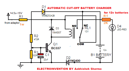
Automatic battery charger Circuit Diagram for 12v
The rectifier /battery chager for power input
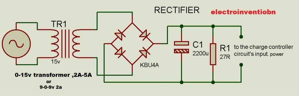
If in some cases, after the rectification and filtration the output voltage can have an increment of about 2v more due to capacitor. If it does, then I prefer to use the LM7815 voltage regulator circuit ( 1amps limit) or LM338 High power variable PSU circuit( 2- 5Amps) ( both are explained on the site.) I still recommend using either 15v DC ready-made adaptor or use the LM7815 Regulator circuit or LM338 high power variable PSU circuit.
Materials
- Q1 Transistor Bc547 or bc337(337 will be preferred more)-1pcs
- C1 Capacitor 22uf 25volts -1pcs
- R2 Resistor 470R – 1pcs
- R3 300R -1ps
- RL1 Relay 12V
- R1 3.3 Ohm or 3R3, 1 Watt or 2 watts -1pcs
- D3 1N4007
- R4 2K-5K
- D1 BZ5242B or any 12v 1w Zener diode
- D2 1N5400-1pcs
- D4 LED-RED
- Transformer 0-15V,2Amp-5Amp ( for battery charging rectifier. BUT I RECOMMEND 15V DC 1A OR 2 A DC ADAPTOR SO THAT IT HAS REGULATED VOLTAGE ) or use LM338 Variable PSU Circuit, 2A-5A for bigger batteries.
- Bridge rectifier diodes 1n5400-4pcs
- Battery suitable (lead-acid,SMF,SLA,GEL CELL,AUTOMOTIVE) 12v , 1.2ah-20 ah
The circuit diagram for charging control and auto-cut as well as a rectifier for power input with a material list is above. I prefer to use a 15v DC 1A or 2A adaptor for perfect voltage and current regulation. Or I prefer to use the LM7815 voltage regulator circuit ( 1amps limit) or LM338 High power variable PSU circuit( 2- 5Amps) ( both are explained on the site.)
Working of the circuit
- In the above circuit, whole charging is governed by BC337 transistor and relay RL1 acts as the changeover.
- During charging the circuits takes input via a charger /bridge rectifier charger circuit shown above and through the relay’s COM and NC, the power is directly connected to the battery.
- After the battery reaches a certain level the transistor bc547 id tuned ON and it drives a relay which in turn changes the COM pin’s link from NC to NO which is connected to the red color LED that will start glowing after relay changeover, indicating the battery charging completion.
- I have set this circuit’s calibration at 13.8v last voltage. When the battery reaches 13.7 or 13.8v then suddenly charging stops and red color led glows as an indication for full charging.
- Below is the image showing how the circuit cuts off the charging when the battery reaches 13.7 or 13.8v.
when the battery is more than 13.7v
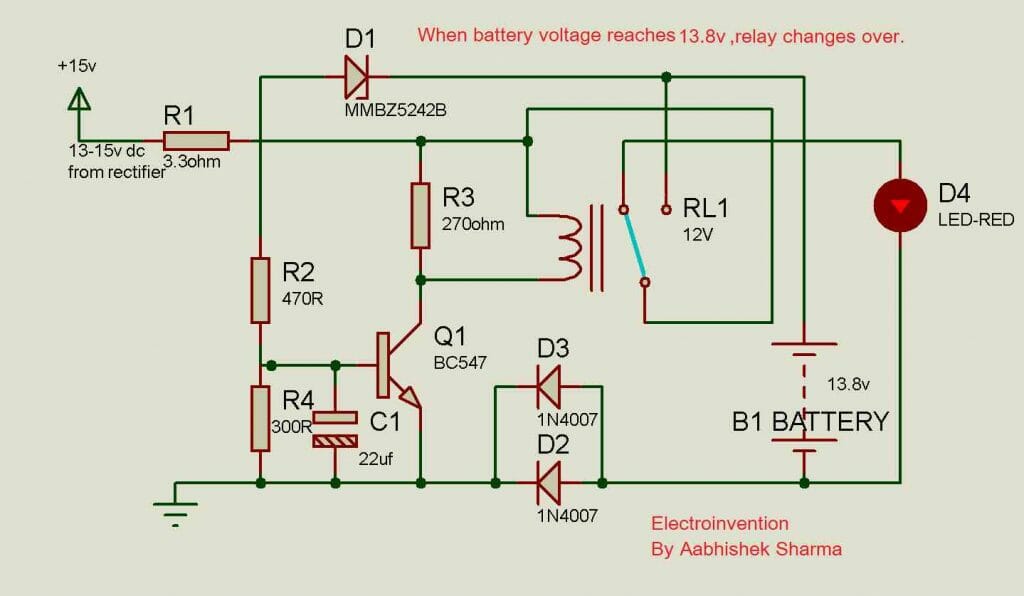
The above image during the simulation when the battery voltage reaches above 13.7 volts i.e when the battery tries to reach 13.8v suddenly transistor BC337 turns ON the relay and charging stops and red led starts getting power. This is how the circuit works. I hope this circuit might be very useful to you guys and you liked it.
The adequate amount of current and charging voltage should be there to perfectly charge a battery under safety. Charging modes also matter like constant-current charge, topping charge and float charge.
For charging a 12v lead-acid battery, the adequate charge voltage must be 14v-14.7v dc and charging cut-off voltage can be from 13.7v – 14v dc. The same is for an inverter battery.
For the charging current specs charging current should be 10% of the Ah rating of the battery. So, for example, to charge a 12v 10ah battery you need a charger of 14v and 1Amp as an adequate and calculated rating charger. But the practical condition differs from the bookish info. So, you can go up to 14v and 1.5A charger for adequate and safe charging that may charge your battery in 5.7 hours approx.
Note: An improvement to this circuit can be made: https://www.electroinvention.co.in/automatic-battery-charger-auto-cutoff#comment-1874 By Mr. V.Sambath Kumar
If you liked it or if you have any questions then please do comment down and let me know. Cheers and the next tutorial is coming soon on the site.
Hi,
Nice work.
I think when the load is connected directly to the battery and power is available we should have an schmit trigger effect. If not the relay will oscillates around the threshold voltage. therefore we should have two threshold values.(as schmitt trigger graph)
is it right?
HI Aabhishek
I suggest you to change the value of C1 to 100mfd 25v this wont creat any time delay hold on problem for the rly. change R2 to1.5k and R3 to a 5k pot and also change R1 to 470 ohms 1watt . It is better to limit the in put dc voltage to a max of 14.2v it is better 14v for a safer side you can series IN 5403diodes for this the forward drop of this is 1.1v at 1.0A DC calculate the required diodes as per your in put voltage, your ckt cocept really good keep it up.
Regards V.Sambath kumar,
Hello, thanks for visiting this website, I will quote your comment in the post itself, as an improvement so that other visitors can get to know about this modification for betterment. Thanks for your advice.
Sir I’m a novice when it comes to electronics. It’s only my hobby. Please how can I use this same circuit to charge a 200Ah inverter battery? Please do the modification for me.
Regards.
Hello Daniel, Thanks for commenting and this circuit is not at all suitable for 200ah. I will post a suitable circuit for that.
Sir thank you very much for the prompt response. I’m waiting for that circuit. Bye.
NIce
Sorry sir, but this circuit is not working with 15v dc supply(whether it is 15v 1amp adapter or 7815 circuit dc supply).
With 15v 1amp dc supply(14.7 to14.9v), the relay constantly flickering and output is 4v to 5v.
I also have tried with 15v 500ma dc (14.6v to 14.87v). But the result is same, the relay constantly flickering, and output 4v to 5v.
But this circuit is working with “12v 1amp” dc, even I have tried with “12v 3amp” dc supply.
Applying “12v 1amp” or “12v 3amp”, I’m getting 11.3v output voltage for battery charging. So ampere is not the problem here.
Hello Sujoy, I assume that you have made the circuit exactly the way it is because it’s working with me and other visitors.
We have to power it from a 15V supply to charge a 12v battery or keeping it topped up 13.4V and it’s better if it’s 14v (but I have set the values here to cut-off at 13.4V. Another reason is when the battery level crosses the 12V, the Zener D1 starts to conduct in reverse, and still, the battery keeps charging until there is enough current thereafter R2 to turn ON BC337 and hence transistor changes the Relay.
In case if it’s not working with you,(cause it’s electronics and sometimes things are messy) I suggest trying checking all the connections and making it on a separate board. Also, this time add a 1N4007 before the relay, just as shown in the google drive link I am uploading: https://drive.google.com/file/d/1G5f8-HN7N8cvgsYg9-7mXY-hNreVilL6/view?usp=sharing
It will cut off at 13.4V.
I hope this will work good luck. Keep in touch and keep updating me on this. Hope this should help you out.