There are tons of LED flasher circuits over the internet, some works and some don’t. Some are consistent and some of them are just useless. So guys, today we will make 2 different types of LED flasher circuits that are self-tested.2 Different LED flasher circuits.
Astable Oscillator Led Flasher (transistor led flasher) – Circuit 1
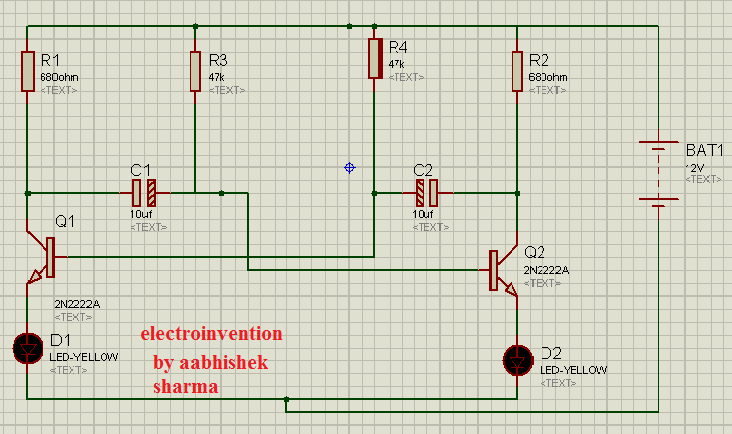
This circuit is employing an AMV(Astable Multivibrator )Oscillator concept, which is also a free-running oscillator as well as a flip-flop. This is also a simple transistor circuit that is easy to make and understand. Below are the materials and the circuit diagram with an explanation.

- Q1,Q2 2N2222A (NPN) 2 PCS
- LEDs 2pcs any color
- C1,C2 10uf 25v-2pcs
- R1,R2 680Ohm -2 pcs
- R3,R4 47K -2PCS
- Battery 9v -12v
How Does It work?
Q1 is in ON state. The LED on the right side D2 starts glowing and when the transistor Q2 is on the D1 starts glowing. Resistors R1 and R2 in the circuit diagram controls the LED current. The voltage of C2 controls transistor Q1. The voltage of C1 controls transistor Q2. When transistor Q1 turns ON, it changes the voltage of C1 so that Q2 goes to saturation or cutoff. The voltage of C1 rises back up and turns on the transistor Q2. When transistor Q2 turns on, it changes the voltage of C2 so that Q1 turns off.
IC 555 LED Flasher Circuit-2

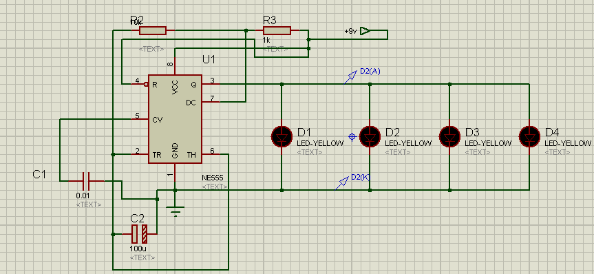
Circuit by using IC555 as an oscillator same concept as above but the difference is a circuit.
- ICNE555
- LEDs
- C1 0.1uf CERAMIC
- C2 100uf ELECTROLYTIC
- R2 10K
- R3 1K
- 9V TO 12V Battery
- there is no R1 actually R2 is R1 and R3 in the diagram should be R2, that’s only labeling mistake sorry.
I HOPE YOU ENJOYED IT, and if you liked it, then please tell me in comments and if there are any questions you can comment on them. Below is my youtube for this project just for reference.


Informative though
thanks for visiting rishi.