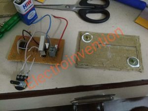
The following circuit shows, how to control the speed of DC motor using IC555 by the implementation of Pulse width Modulation.DC motors are used in many devices and applications in our surroundings for eg.toy cars, car wipers, Electric automotive vehicles, etc..Some devices have automatic speed adjustment systems, but in some applications, we need to adjust the speed via potentiometers. So let’s begin with our IC555 Motor speed controller or IC555 motor speed controller using Pulse Width Modulation.

Pulse Width Modulation and working
PWM is a method through which we can generate variable voltage by turning on and off the power that’s going to the electronic device at a fast rate. The average voltage depends on the duty cycle of the signal, or the amount of time the signal is ON versus the amount of time the signal is OFF in a single period of time. The 555 Timer is capable of generating a PWM signal when set up in an astable mode.
The PWM pulses are generated by ic555 and due to varying resistance, the duty cycle is also varied. this results in variation in output voltage as the PWM pulses are fed to MOSFET GATE.HENCE, change in duty cycle causes a change in motor speed as output power also varies with current.
Higher the duty cycle the average voltage across motor will be high which results in higher motor speed and lower duty cycle results lower motor speed.
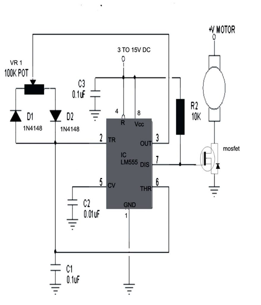
The circuit diagram

Components
| 1 | IC555 | 1pcs |
| 2 | MOSFET | IRF540N |
| 3 | C1,C3 0.1uf | 1pcs |
| 4 | C2 0.01uf | 1pcs |
| 5 | D1, D2 1N4148 (zener) | 2 pcs |
| 6 | VR1 2K | 1pcs |
| 7 | R2 10k | 1pcs |
| 8. | Flyback diode with MOSFET: 1N5822 | 1pcs |
| 9 | PCB,Battery 12v | 1 |
Guys if you like this, please let me know in comments, if you have any doubts, you can comment them below. I have also added a working video of this project made by me.


This blog IC555 Motor speed controller using PWM helps me a lot with my battery problems.
Khub bhalo hoyche